![]() Buried Single Layer Capacitors data sheet in PDF format.
Buried Single Layer Capacitors data sheet in PDF format.
|
Buried Single Layer™ Capacitors |
Presidio Advantage |
|
|
|
Kent Simulator |
|
Using the KENT SIMULATOR, a designer can obtain commonly needed RF capacitor parameters in graphical format for popular Presidio Components RF capacitors. In addition, S-parameters for selected capacitors can be saved in S2P format. All device parameters are derived from a series transmission line model developed by Dr. Gordon Kent and is available for download. A technical discussion of the simulation used in the Kent Simulator is presented by Dr. Kent in the "Summary of the Capacitor Simulator." |
|
Kent Simulator Version 2.0: LSA1010B101MGH5R- |
|
Typical Applications |
|
Filter Capacitor |
|
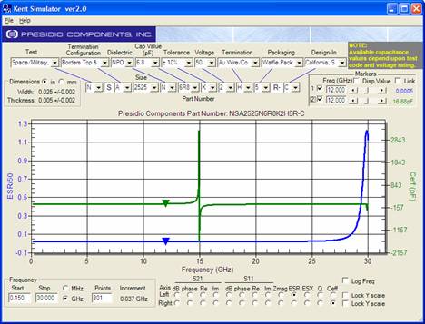
Modeled ESR/50 and Ceff of part NSA2525N6R8K2H5R-, Class I dielectric. |
|
Resonance-Free Broadband Coupling/Decoupling Capacitor |
|
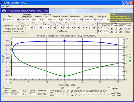
Class II "BX" dielectric is typical for DC block or RF bypass applications to operate resonance free over a specified broad frequency range. Low impedance is typically more important than the capacitance value which should be large enough to cover the 3 dB low edge of the bandwidth. |
|
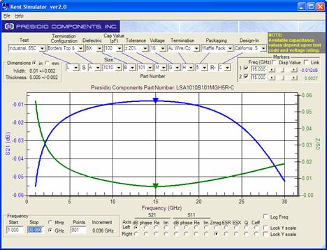
Modeled S21 and Z/50 of part LSA1010B101MGH5R-, Class II dielectric. |
|
Minimum Loss, Finite Band Coupling Capacitor |
|
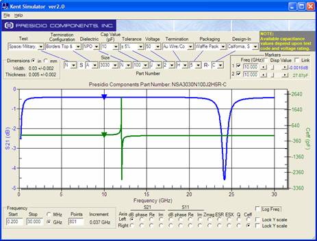
When minimum loss is required, e.g. a low noise circuit, a high Q capacitor with Class I dielectric (NPQ or NPO) is recommended. Any parallel resonance frequency of the capacitor should be outside of the use frequency band. The best capacitor choice puts the series resonance at the band center (approximately f0 / 2). |
|
Modeled S21 and Ceff of part NSA3030N100J2H5R-, Class I dielectric. |
|
|
|
|
|